FACILITIES
The ISTENER Research Group has adaptable test benches in the laboratories that allow them to simulate the typical operating conditions of different refrigeration, air conditioning and heat pump systems, and organic Ranking cycle systems. In addition to these equipment, they also have the required thermal simulation equipment (load and dissipation) to establish the targeted operating conditions.
Laboratory TT2003TL
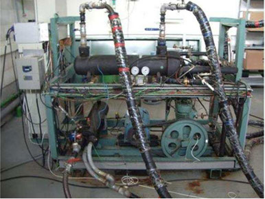
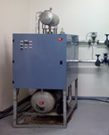
VAPOR COMPRESSION SYSTEM
This test bench simulates the behavior of a refrigeration system based on a medium power vapor compression system that can cover low and medium evaporation temperatures (food conservation and freezing). The main components of the equipment are an open-type reciprocating compressor, which is driven by a 7.5 kW electric motor which equipped with a frequency inverter; a plate evaporator and a shell and microfin tube condenser; and thermostatic expansion (R134a and R404A) and electronic (R134a) bypassed valves. Other additional components are a liquid-to-suction heat exchanger, dehumifier filter, oil separator, sight glass, safety elements such as pressure switch and relief valve, and load ports. All information necessary to control the proper functioning of the equipment (temperatures, pressures, power consumption and mass flow) is measured and transferred by means of a data acquisition system to a personal computer, where it is monitored and recorded.
HEAT LOAD CIRCUIT

The evaporator is designed to use a glycol based secondary fluid to operate at temperatures under 0 °C. This fluid is heated in a tank by means of a set of electrical resistances that simulate the thermal load. The water-glycol mixture is pumped to the tank through the pump equipped with a frequency inverter. Inside the tank and in the lower part there are three immersion resistors of 5.2 kW each. One of these resistances can be regulated by means of a PID temperature controller. The circuit has a pressure gauge to know the pressure in the tank, and an expansion vessel to absorb the secondary fluid volume variations. As for the instrumentation, since the flow rate and temperatures of the fluid are required, an electromagnetic flowmeter and two K-type surface thermocouples at the inlet and outlet of the evaporator are installed.
HEAT DISSIPATION CIRCUIT
The secondary fluid of this heat dissipation circuit is water that is cooled by a set of commercial heat pump and a fan. The water pump provides to the fluid the circulation necessary along the circuit. The pressure gauge indicates the pressure at which the circuit is located. After the manometer, the dissipation circuit has an expansion vessel for safety, and then, an electromagnetic flowmeter, which is connected to the data acquisition system, and finally the chiller. The volumetric flow rate of the water can be varied manually by means of a balancing valve. The variation of the water temperature is controlled by the fan that is equipped with a frequency inverter.

PCM DEPOSIT
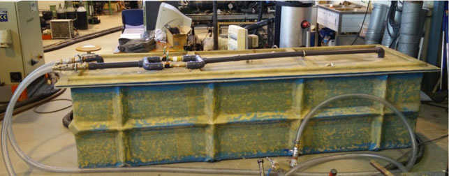
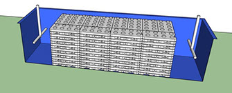
The thermal storage tank consists of a tank made by polymer material, exterior dimensions 3 x 0.75 x 0.75 meters. Inside, there are 192 PCM containers divided into 16 rows of 12 units. The total latent heat of the Phase Change Materials (PCMs) is around 50kWh, a quantity that allows to dissipate 6 thermal kW for 8 hours. The PCM containers have been placed in the center of the tank leaving two spaces of half a meter in length at both ends for the correct homogenization of the water flow (Figure 3.7). The water is introduced and extracted from the tank through T-shaped PVC ducts with multiple perforations to achieve a better water mixing. The PCM currently available is the S27 type of the UK company PCM Products LTd. It is a commercial hydrated salt with a melting point of 27 °C. It is inside of High Density Polyethylene (HDPE) containers and the dimensions are: 500 mm long, 250 mm wide and 32 mm high.
Laboratory TC1014CP
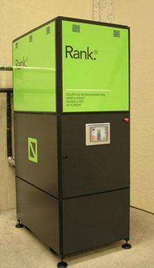
ORC MODULE
The ORC module uses a regenerative configuration and nominal power of its generator is 1.5 kW (see Figure 4.3). This configuration allows to use also the superheating of the vapor at the outlet of the expander to preheat the pressurized liquid prior to entering the evaporator. The ORC module is designed to use thermal oil as a secondary fluid in the hot source and water in the cold source. The working fluids that can be used are HFC-245fa and alternatives to it like HCFO-1233zd-E and HFO-1336mzz-Z. The expansion technology is volumetric type and the heat exchangers are welded plates based. The maximum inlet temperature of the thermal oil is 160 °C and the maximum inlet temperature of the water is 45 °C. The pressure and temperature at the inlet and outlet of the main elements and the mass flow rate of the working fluid are measured by means of a Coriolis mass flow meter. The electrical power generated by the expander and the electric power consumed by the pump are obtained by means of two digital wattmeter. Finally, all measurements are collected through a data acquisition system, then they are recorded and monitored through a personal computer.
HEAT SOURCE CIRCUIT
It consists of a closed circuit of thermal oil whose main component of the circuit is the electric boiler of 12 kW, which provides the thermal power required by the heat source of the dithermic system and controls the inlet temperature of the thermal oil by means of a thermostat. The pump is a centrifugal type that provides the flow to the circuit keeping it fixed for all tests performed. Finally, the thermal oil used is Pirobloc 300-A, a thermal fluid used in liquid phase in indirect processes of heat transfer. The temperature at the inlet and outlet of the main elements and the flow of the water circuit is measured by means of a Vortex flow meter.
WATER HEATING CIRCUIT
It consists of a water closed circuit that can be used independently of the ambient temperature to achieve the desired conditions, thanks to a valve set that controls the circuit, an air heater and a chiller. The air heater, which has a heat exchange surface of 187 m2, dissipates to the environment the thermal power coming from the heat sink of the dithermic system. It sets the inlet temperature of the water by means of a PID controller that varies the frequency of rotation of the fans. The chiller is a water cooling system based on a vapor compression cycle with a cooling capacity of 11.3 kW, which controls the water inlet temperature to the dithermic system. A centrifugal pump provides the flow to the circuit, which is the same for all tests performed. The temperature at the inlet and outlet of the main elements and the flow rate of the water circuit is measured by means of an electromagnetic flow meter.
VAPOR COMPRESSION SYSTEM
This test bench simulates a small/medium cooling capacity vapor compression system that operates at medium-temperature evaporation. It has a scroll compressor equipped with a frequency inverter, designed to be used with HFC-134a and its alternatives such as the HFO-1234yf. Other elements are the condenser and evaporator that are built in plate exchanger technology and the electronic expansion valve designed for HFC-134a. It has the additional elements that ensure the proper functioning of the equipment (filter, sight glass, etc.) and safety elements such as pressure switch and relief valve. The pressure and temperature at the inlet and outlet of the main elements is measured and the mass flow rate of the working fluid is controlled by means of a Coriolis mass flow meter. The electric power consumed by the compressor is obtained directly from the frequency inverter. Finally, all measurements are collected through a data acquisition system, whereby they are recorded and monitored through a personal computer.